door lock circuit Security Circuits Nextgr Circuit Diagram Then a circuit to save each pressed number and toggle between displays ; As well as an internal memory for our password ; And, the hearth of our lock, the comparator (its 8 bits ´cause there are 4 bits per digit in the display, meaning that if you want to do a 4 digit lock you will need two of this connected together.)
Digital Code Locks are very popular in Electronics, where you need to enter a particular 'Code' to open the Lock. This type of Locks needs a Microcontroller to compare the entered code with the predefined code to open the Lock. We have already built these kinds of Digital Locks using Arduino, using Raspberry Pi and using 8051 microcontroller. But today here we are building the Code Lock
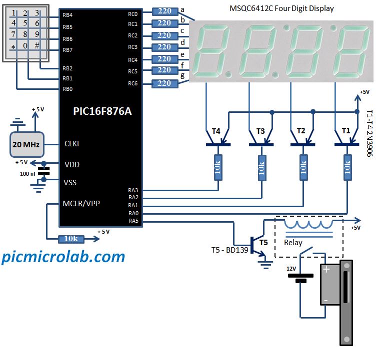
Simple Electronic Code Lock Circuit Circuit Diagram
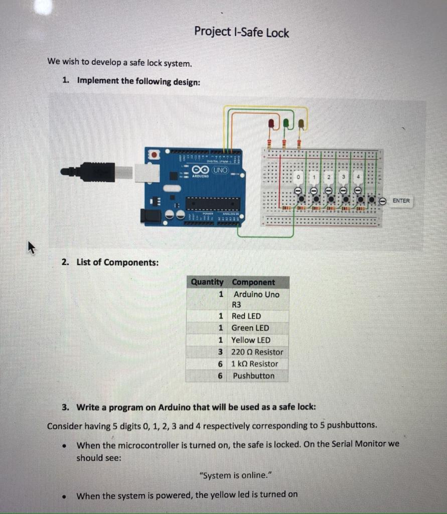
This would signal everyone in the area that someone is tampering with your safe, and allow you to react accordingly. Like my previous project, I will be creating this circuit within TinkerCAD, a free-to-use online modelling program that allows you to create circuits electronically. However, since this instructable is still based off a circuit The project is simple and easy; Applications. This simple timer-based electronic code lock circuit has usage in residential places to ensure better safety. It has been used by organizations to ensure authorized access to highly secured places. With a slight modification, this will control the switching of loads through a password.
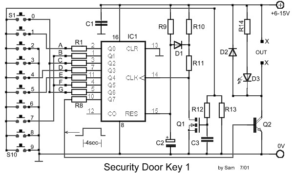
Default Password: 21345. Circuit Description: The proposed electronic lock circuit consists of just few components; an IC 4017 which is the heart of the circuit, 11 push buttons for entering the pin number, 5 diodes to prevent short-circuit between output pins, couple of LEDs for indicating the status whether the circuit is locked or unlocked, couple of pull-down resistors, couple of current
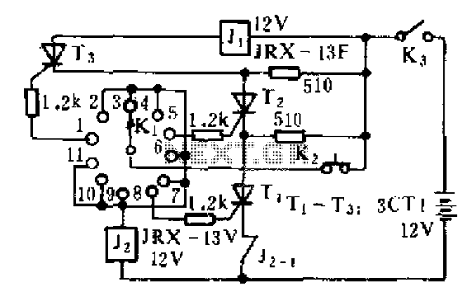
Simplest Combination Lock Circuit Explained Circuit Diagram
This electronic code lock circuit is characterized by its basic design employing a notable code implementation with just a single active component and a minimum of 8 button switches.. How does the circuit of the code lock operate? In order to activate the relay, all four buttons S1 to S4 need to be pressed simultaneously.. If any of the buttons from S5 to S8 are pressed, the relay remains